
TM 5-3990-263-13&P
0008
OPERATION - Continued
WARNING
Keep hands and fingers clear of front pin lock assemblies when in the auto engaged and
disengaged position. Failure to comply may result in serious injury or death to personnel.
NOTE
To release front pin lock assemblies, movement of the LHS hook arm may be required.
12.
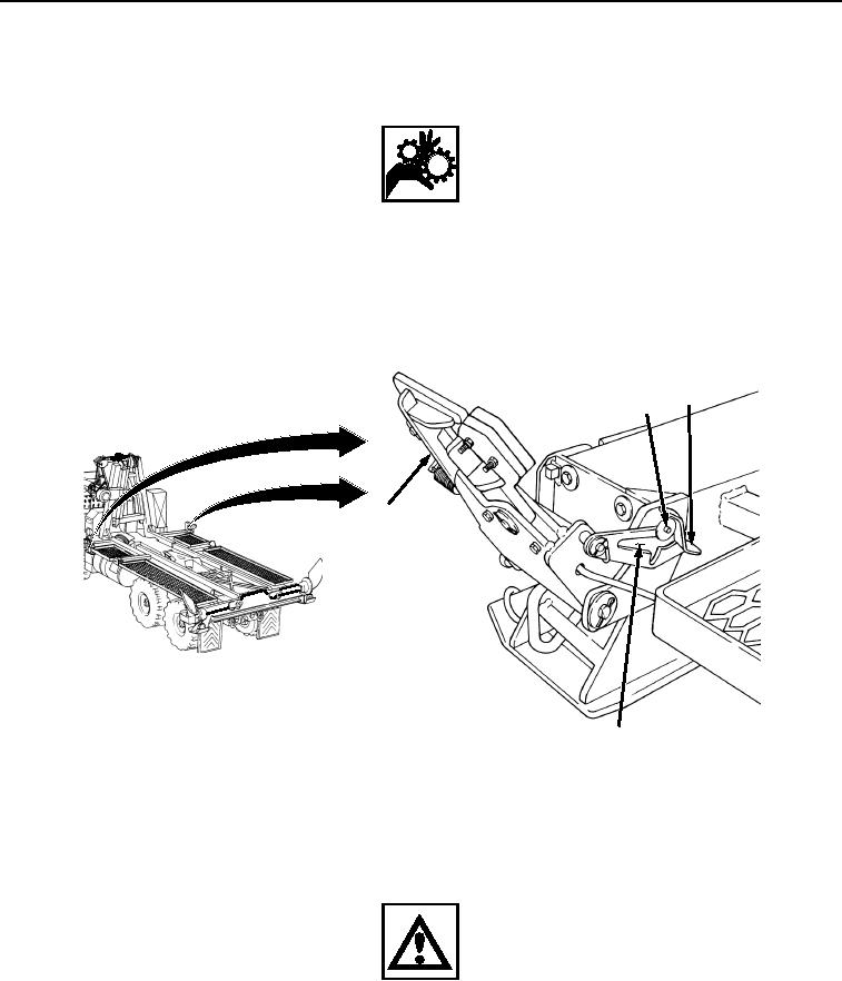
Release curb-side and road-side front pin lock assemblies (Figure 8, Item 20):
19
21
20
22
Figure 8.
Front Pin Locks.
Press latch levers (Figure 8, Item 19) down, and pull back front pin lock assemblies (Figure 8, Item 20)
until latch lever pin (Figure 8, Item 21) rests at top of vertical slot (Figure 8, Item 22).
WARNING
After releasing rear guides, only winch hook secures bridge bay to the BAP. Personnel must
not mount the BAP and must stay clear of the area around rear of vehicle. The load could
shift, release, or fall. Failure to comply may result in serious injury or death to personnel.
13.
Set curb-side and road-side rear guides (Figure 9, Item 23) to full open position:
03/15/2011Rel(1.8)root(opusualwp)wpno(O01057)