
TM 5-3990-263-13&P
0008
OPERATION - Continued
31
30
28
18
29
27
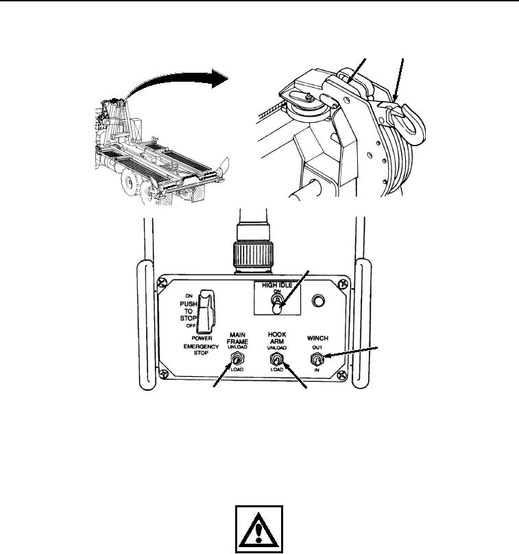
Figure 12.
Stowing Winch Cable.
23.
Set HIGH IDLE switch (Figure 12, Item 28) to ON position. Position MAIN FRAME switch (Figure 12, Item 29)
to LOAD.
24.
As main frame moves to stowed position, set HIGH IDLE switch (Figure 12, Item 28) to OFF.
WARNING
When NO TRANSIT indicator is illuminated, vehicle may be maneuvered in the immediate
vicinity of the loading/unloading site. However, vehicle is unsafe for road travel. Do not
perform open-road driving when NO TRANSIT indicator is illuminated. Failure to comply may
result in serious injury or death to personnel and damage to equipment.
25.
Position HOOK ARM switch (Figure 12, Item 27) to LOAD until LHS hook arm has been fully stowed.
03/15/2011Rel(1.8)root(opusualwp)wpno(O01057)