• Home
  • Download PDF
  • Order CD-ROM
  • Order in Print
Figure 15. Setting Front Pin Locks.
BRIDGE BAY LAUNCHING INTRODUCTION

Parts Manual For Pallet, Adapter, Bridge M15 Page Navigation
  61    62    63    64    65  66  67    68    69    70    71  
img
.
TM 5-3990-263-13&P
0008
OPERATION - Continued
29.
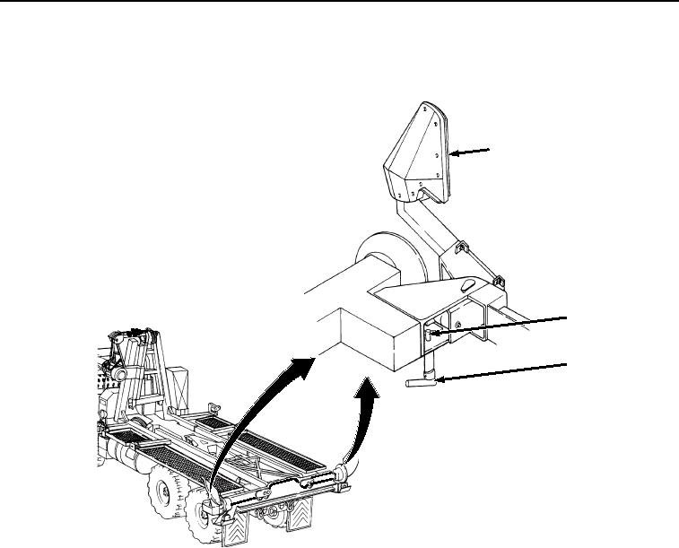
Secure curb-side and road-side rear guides (Figure 16, Item 23) to their stowed position:
23
25
24
Figure 16. Stowing Rear Guides.
a.
Rotate latch pin (Figure 16, Item 24) until rear guide (Figure 16, Item 23) disengages.
b.
Swing rear guide (Figure 16, Item 23) to full inboard position, and ensure pin (Figure 16, Item 25) clicks
into hole.
END OF TASK
END OF WORK PACKAGE
0008-17/18 blank
03/15/2011Rel(1.8)root(opusualwp)wpno(O01057)


Privacy Statement
Press Release
Contact

© Copyright Integrated Publishing, Inc.. All Rights Reserved.