• Home
  • Download PDF
  • Order CD-ROM
  • Order in Print
Figure 14. Stowing Remote Control Unit
Figure 16. Stowing Rear Guides.

Parts Manual For Pallet, Adapter, Bridge M15 Page Navigation
  60    61    62    63    64  65  66    67    68    69    70  
img
.
TM 5-3990-263-13&P
0008
OPERATION - Continued
19
21
20
22
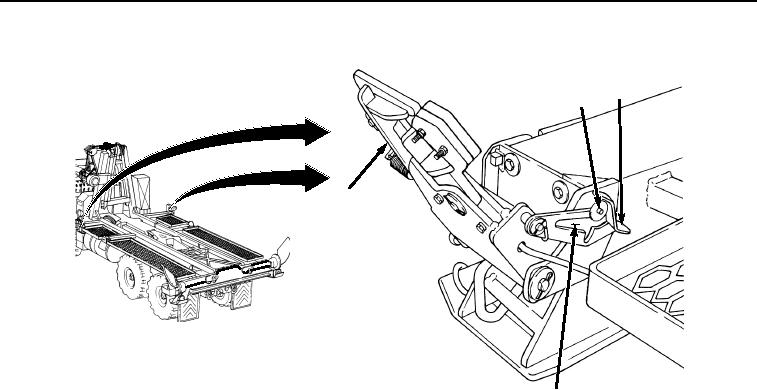
Figure 15. Setting Front Pin Locks.
a.
Pull front pin lock assembly (Figure 15, Item 20) toward you while moving latch lever (Figure 15, Item
19) to center position.
b.
Allow front pin lock assembly (Figure 15, Item 20) to slide inboard.
0008-16
03/15/2011Rel(1.8)root(opusualwp)wpno(O01057)


Privacy Statement
Press Release
Contact

© Copyright Integrated Publishing, Inc.. All Rights Reserved.