
TM 5-3990-263-13&P
0010
OPERATION - Continued
19
20
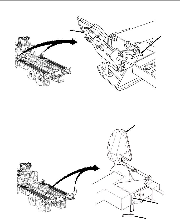
Figure 17.
Secure Front Pin Locks.
40.
Pull front pin lock assembly (Figure 17, Item 19) to release latch lever (Figure 17, Item 20), then let lock move
in.
41.
Secure curb-side and road-side rear guides (Figure 18, Item 23):
23
25
24
Figure 18. Secure Rear Guides.
a.
Rotate latch pin (Figure 18, Item 24) until rear guide (Figure 18, Item 23) disengages.
03/15/2011Rel(1.8)root(opusualwp)wpno(O01058)