TM 5-3990-263-13&P
0010
OPERATION - Continued
CAUTION
When moving LHS hook arm rearward, ensure winch hydraulic hose lines are not trapped or
damaged. Failure to comply may result in damage to equipment.
20.
Position HOOK ARM switch (Figure 12, Item 29) to UNLOAD and release when both hook arm cylinders (Figure
12, Item 30) are extended approximately 6 in. (15 cm).
21.
Position MAIN FRAME switch (Figure 12, Item 31) to UNLOAD and release when bridge bay is clear of vehicle
and the BAP.
22.
Position WINCH switch (Figure 12, Item 22) to OUT and release when bridge bay floats.
NOTE
Refer to TM 5-5420-209-12 or TM 5-5420-278-10 for bridge bay operations.
23.
Have boat crew move in toward bridge bay and install pin and lanyard in secured travel latch.
24.
Position MAIN FRAME switch (Figure 12, Item 31) to UNLOAD and release when there is enough slack in
cable to remove cable hook (Figure 12, Item 14) from bay lifting eye (Figure 12, Item 15).
25.
Set HIGH IDLE switch (Figure 12, Item 28) to OFF position.
26.
Have boat crewman remove winch cable hook (Figure 12, Item 14) from bay lifting eye (Figure 12, Item 15).
WARNING
After water operations, vehicle brakes will be wet and will not stop as quickly as usual. Care
must be taken and extra distance allowed for slowing or stopping vehicle. Failure to comply
may result in serious injury or death to personnel and damage to equipment.
27.
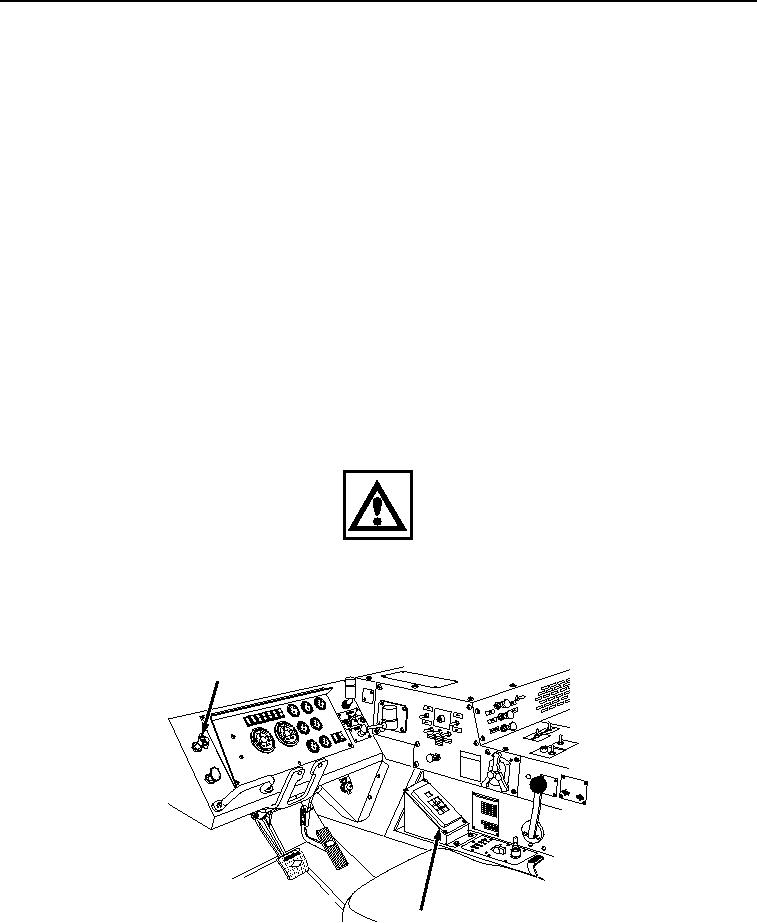
Push in PARKING BRAKE control (Figure 13, Item 26) and drive vehicle forward until clear of water. Stop
vehicle.
26
JACO
BS
ENGIN
EBRA
KE
CAUT
ION
XHA
OE U
ILER Y
TRA PPILG
RSUANK
N
AIOTFORPARD
L
MID
N
US
HTO
27
Figure 13. Brake and Transmission Controls.
28.
Set transmission range selector (Figure 13, Item 27) to neutral.
03/15/2011Rel(1.8)root(opusualwp)wpno(O01058)

