
TM 5-3990-263-13&P
0014
OPERATION - Continued
4
5
Figure 2.
Lock Winch Frame to BAP.
a.
Remove lockpin (Figure 2, Item 5) from each locking lever (Figure 2, Item 4).
b.
Swing locking lever (Figure 2, Item 4) to the up position.
c.
Insert lockpin (Figure 2, Item 5) into locking lever (Figure 2, Item 4).
6.
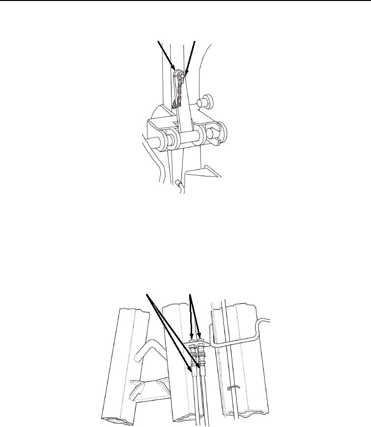
Ensure two hydraulic hoses (Figure 3, Item 6) are secured to the stowed location connections (Figure 3, Item
7).
6
7
Figure 3. Stow Hydraulic Hoses.
03/15/2011Rel(1.8)root(opusualwp)wpno(O01065)