
TM 5-3990-263-13&P
0014
OPERATION - Continued
33.
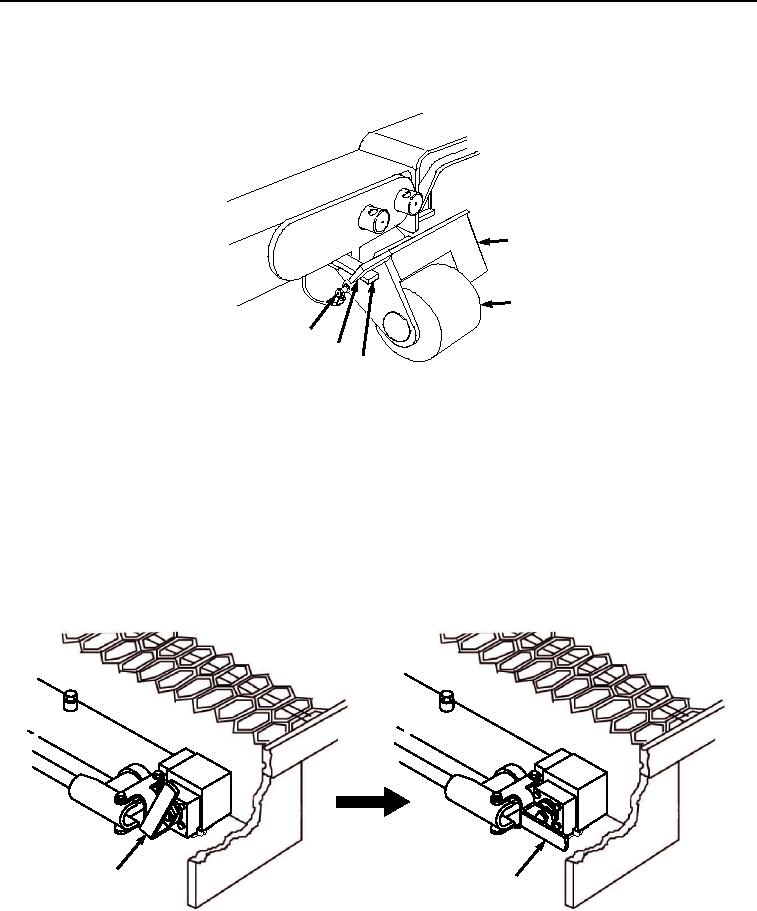
Stow curb-side and road-side transload rollers (Figure 10, Item 27):
31
27
28
30
29
Figure 10. Stow Transload Rollers.
a.
Remove lockpin (Figure 10, Item 28) from stowed position on transload rollers (Figure 10, Item 27).
b.
While holding transload roller (Figure 10, Item 27), swing retainer bar (Figure 10, Item 29) free of notch
(Figure 10, Item 30) on transload rollers (Figure 10, Item 27).
c.
Swing transload roller (Figure 10, Item 27) into stowed position, and install lockpin (Figure 10, Item 28)
in transload rollers (Figure 10, Item 27).
d.
Swing transload bracket (Figure 10, Item 31) up against lockpin (Figure 10, Item 28).
e.
Move hand pump selector valve lever (Figure 11, Item 12) to center roller UP position, to allow extension
cylinders to retract fully.
12
12
Figure 11. Retract Transload Roller Cylinders.
03/15/2011Rel(1.8)root(opusualwp)wpno(O01065)