
TM 5-3990-263-13&P
0031
CORRECTIVE ACTION - Continued
JACO
BS
ENGIN
EBRA
KE
CAUT
ION
XHA
OE U
ILER Y
TRA PILG
RSUPND
N
ANIOTFORDPARK
ILA
M
US
HTO
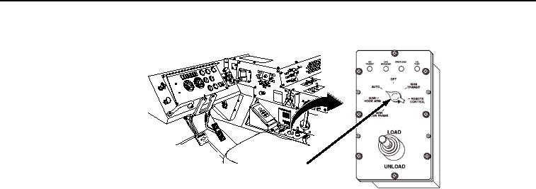
CAB LHS MODE
SELECT SWITCH
Figure 4. Cab Digital Mode Select Switch.
9.
Place positive (+) probe of multimeter on position 3, circuit 1471, of control cab control box
connector J2 (Figure 3). Note reading.
NOTE
Position 4, circuit 1490, should have a reading of 1 - 5 volts, not 22 - 28 volts. If 1
- 5 volts are not measured at position 4, replace the cab digital control box.
(TM 9-2320-435-10 or TM 9-2320-425-10)
10.
Place positive (+) probe of multimeter on position 4, circuit 1490, of control cab control box
connector J2 (Figure 3). Note reading.
11.
Turn engine start switch to OFF position. (TM 9-2320-435-10 or TM 9-2320-425-10)
a.
If 22 - 28 volts is not present at connector J2 position 2 and position 3, repair or replace cab
interface wiring. (TM 9-2320-435-10 or TM 9-2320-425-10)
b.
If 22 - 28 volts is present at connector J2 position 2 and position 3, proceed to next
Malfunction.
MALFUNCTION
Wiring Between Connectors J4 and P2 is Faulty and/or Wiring Between Connector J3 and WINCH OUT
Solenoid is Faulty.
CORRECTIVE ACTION
CAUTION
Electrical power must be shut OFF from circuit before continuity can be checked.
Failure to comply with this caution may result in damage to test equipment or
electrical system.
NOTE
Digital controller and cab control box are not repairable, therefore, it is necessary
to test digital controller and cab interface wiring harnesses, switches, solenoids,
and other components to identify possible faults other than digital controller and
digital cab controller.
1.
Remove 6 screws and flatwashers from hydraulic cabinet cover and remove cover (Figure 5).