
TM 5-3990-263-13&P
0031
MALFUNCTION
Wiring Between Connector J3 and WINCH IN Solenoid is Faulty.
CORRECTIVE ACTION
CAUTION
Electrical power must be shut OFF from circuit before continuity can be checked.
Failure to comply with this caution may result in damage to test equipment or
electrical system.
NOTE
Digital controller and cab control box are not repairable, therefore, it is necessary
to test digital controller and cab interface wiring harnesses, switches, solenoids,
and other components to identify possible faults other than digital controller and
digital cab controller.
1.
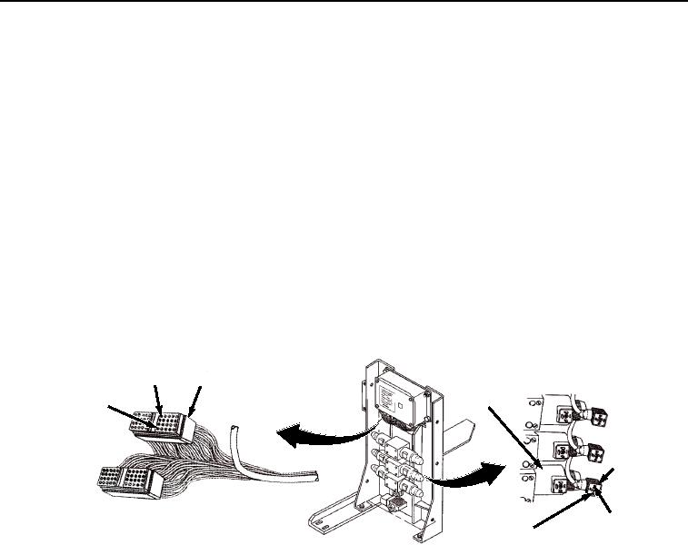
Remove connector from WINCH IN solenoid (Figure 8).
POSITION
WINCH IN
J3
36
VALVE AND
POSITION
SOLENOID
6
WINCH IN
SOLENOID
CONNECTOR
POSITION 1
POSITION 2
Figure 8. Connector J3.
2.
Set multimeter to ohms position.
NOTE
A reading of infinity indicates an open circuit.
3.
Place negative (-) probe of multimeter on position 6 of digital controller wiring harness connector
J3 (Figure 8).
4.
Place positive (+) probe of multimeter on position 1 of WINCH IN solenoid connector (Figure 8).
Check multimeter for continuity.
5.
Place negative (-) probe of multimeter on position 36 of digital controller wiring harness connector
J3 (Figure 8).
6.
Place positive (+) probe of multimeter on position 2 of WINCH IN solenoid connector (Figure 8).
Check multimeter for continuity.
a.
If continuity is not present at one or both readings, repair or replace digital controller wiring
harness. (TM 9-2320-435-10 or TM 9-2320-425-10)
b.
If continuity is present for both readings, proceed to next Malfunction.