
II113300-1-103
Rev. A
f)
Using the lifting strap and material handling equipment (hoist, forklift, etc.), position the
Armored Roof Assembly over the cab and carefully lower it into position. Use a drift
pin(s) to line up the bolt holes around the perimeter of the Escape Hatch opening.
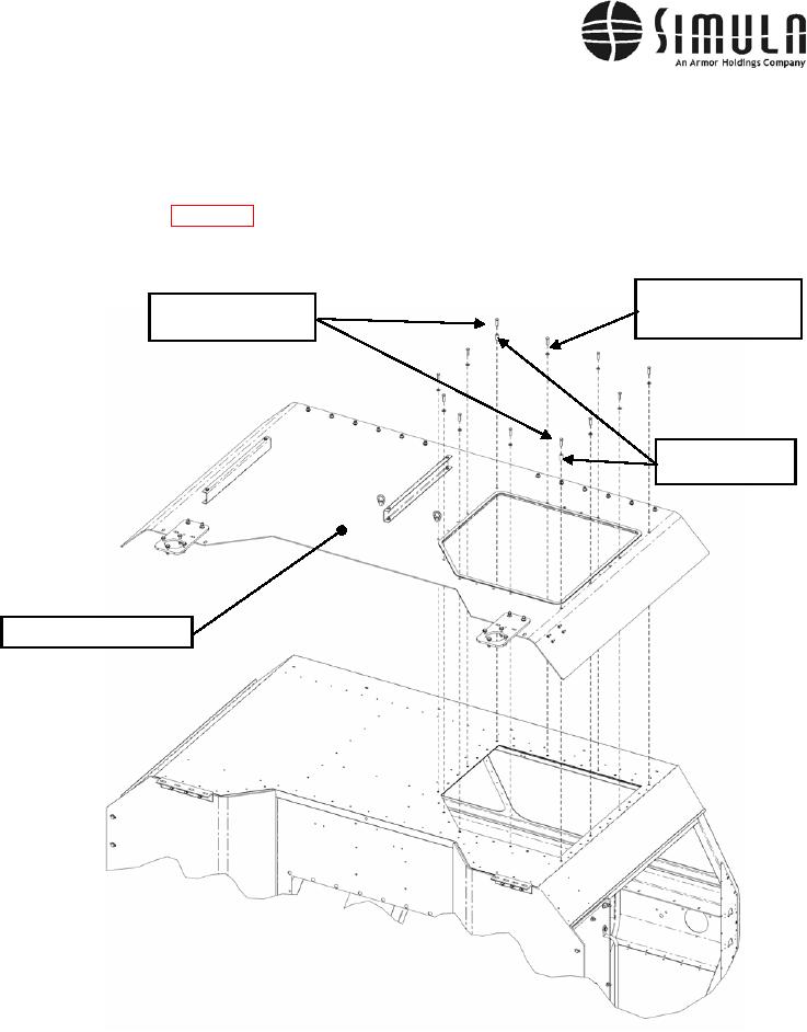
g) Once all the holes are lined up, insert the bolts and two Standoffs (P/N 8080r S .5 35) as
shown in Figure 41, but do not fully tighten them. The bolts will be fully tightened once
the two Rear Armor Panels have been attached to the Armored Roof Assembly panel.
Bolt, Hex Head,
Bolt, Hex Head,
0.312-18 x 1.250 Long,
0.312-18 x 1.750 Long
Washer 0.312 ID
Standoff (Qty 2),
P/N 8080R S .5 35
Armored Roof Assembly
Figure 41. Armored Roof Panel installation.
h) Attach the Left Rear Panel to the roof using the hardware shown in Figure 42. Do not
fully tighten the bolts at this time. Tighten the bolts such that the top of the top surface of
the angled bracket is 0.00 to 0.60 in. from the bottom surface of the roof panel.
0037 00-70