
II113300-1-103
Rev. A
NOTE
When installing the Rear Right Panel to the Armored Roof Panel,
loosen the two bolts that attach the Side Rear Panel Assembly to
the Right Rear Panel. This will allow the parts to move into the
correct position as the bolts shown in Figure are tightened.
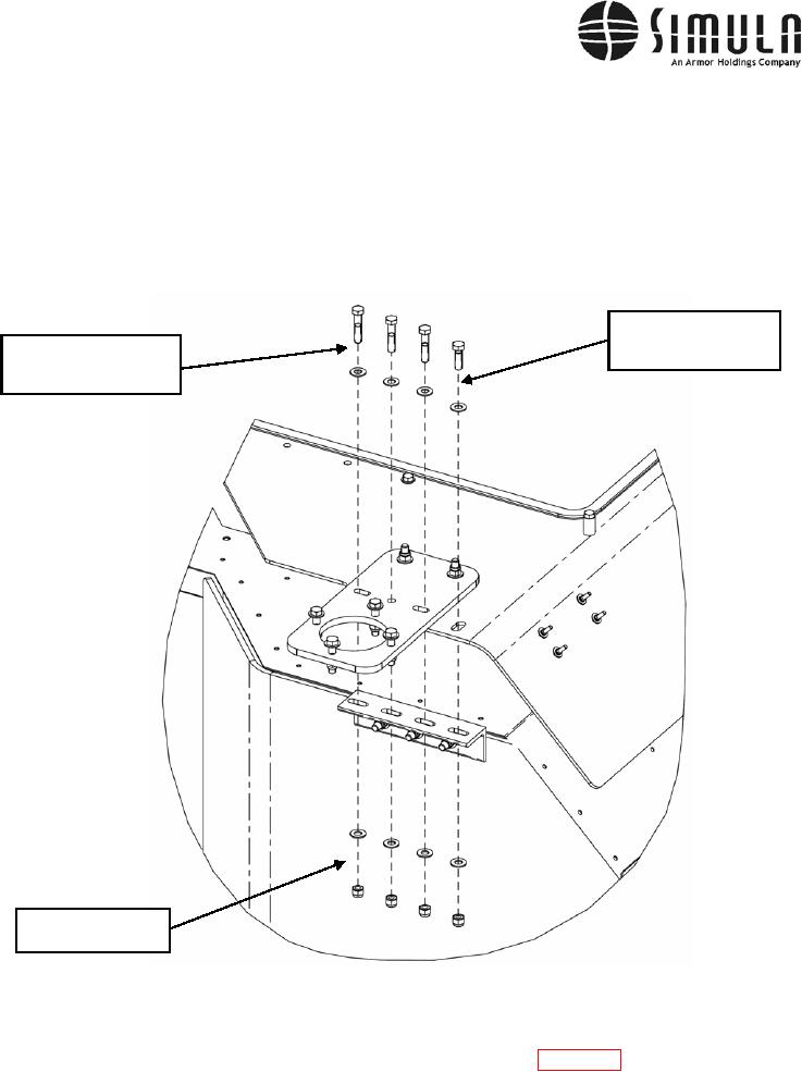
Bolt, Hex Head (Qty 1),
0.375-16 x 1.250 Long,
Bolt, Hex Head (Qty 3),
Washer 0.375 ID
0.375-16 x 1.750 Long,
Washer 0.375 ID
Lock Nut 0.375-16,
Washer 0.375 ID
Figure 43. Installing the Antenna Mount, Right Side.
j)
Install the Draw Latch Component (P/N F7-51) shown in Figure 44 on each of the four
Escape Hatch Brackets (P/N 113357-1) using 0.190-24 X 0.750-in.-long Hex Head Bolts
and washers, as shown in Figure 44. Torque the fasteners to 3 ft-lb.
0037 00-72