
II113300-1-103
Rev. A
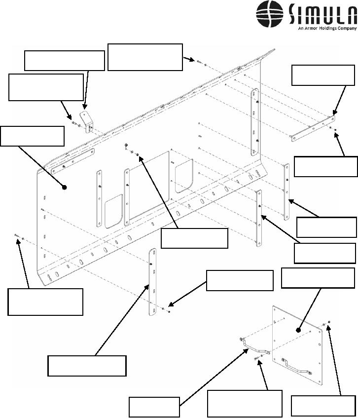
Bolt, Hex Head,
Blackout Light Bracket,
0.250-20 x 1.250 Long,
P/N 113355-1-103
Washer 0.250 ID
Stud Plates,
P/N 113375-1-103
Bolt, Hex Head,
0.375-16 x 1.250 Long,
Washer 0.375 ID
Lower Brush Guard,
P/N 113371-1-103
Lock Nut 0.250-20,
Washer 0.250 ID
Stud Plates,
P/N 113375-1-103
Lock Nut 0.375-16,
Washer 0.375 ID
Stud Plates,
P/N 113375-9-103
Winch Cover Panel,
Lock Nut 0.250-20,
P/N 113373-1-103
Washer 0.250 ID
Bolt, Hex Head,
0.250-20 x 1.250 Long,
Washer 0.250 ID
Spacer, Brush Guard,
P/N 113376-1-103
Bolt, Hex Head,
Lock Nut 0.312-18,
Grab Handle,
0.312-18 x 1.250 Long,
Washer 0.312
P/N 31-8-BLK
Washer 0.312 ID
Figure 47. Lower Brush Guard and Winch Cover.
f)
Apply Urethane Sealant (P/N 104302-1) around the perimeter of the light openings and
install the Light Cover Plates (P/N 113379-1-103) using the hardware shown in
Figure 48.
0037 00-76