
II113300-1-103
Rev. A
CAUTION
Do not over-torque the fasteners. This will strip the threaded hole
in the Draw Latch Component.
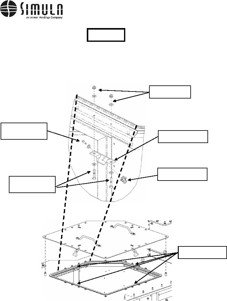
k) Install the four Bracket Assemblies using the hardware shown, and in the locations
shown, in Figure 44. Do not fully tighten the bolts at this time.
Lock Nut 0.250-20,
Washer 0.250 ID
Bolt, Hex Head,
0.190-24 x 0.750 Long,
Escape Hatch Bracket,
Washer 0.190 ID
P/N 113357-1
Draw Latch Component,
P/N F7-51
Bolt, Hex Head,
0.250-20 x 1.500 Long,
Washer 0.250 ID
Escape Hatch Bracket
Assembly Locations (4)
Figure 44. Installation of the Escape Hatch Brackets.
0037 00-73