
II113300-1-103
Rev. A
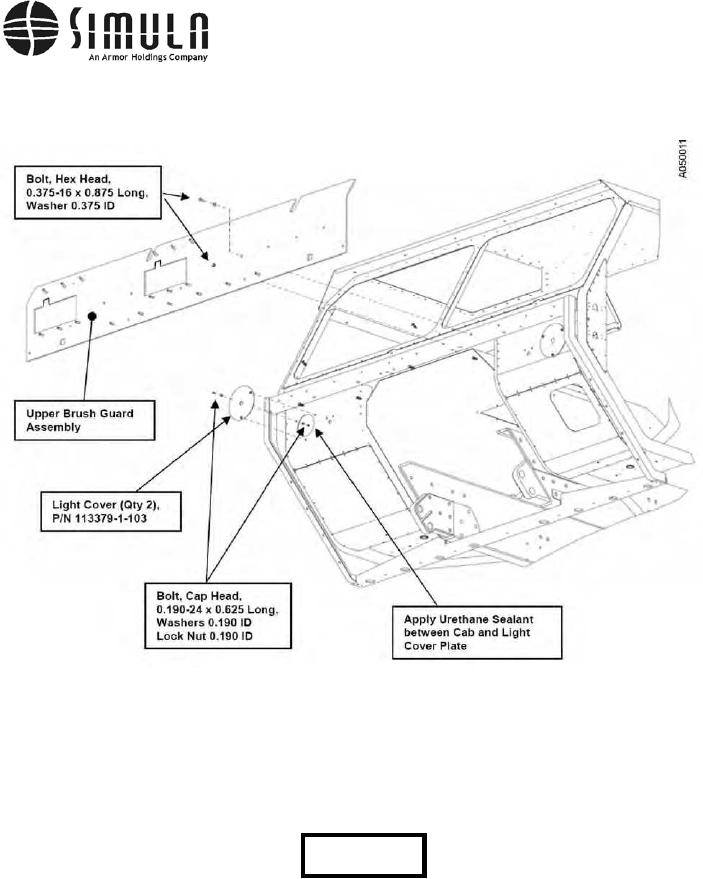
g) Install the Upper Brush Guard Assembly using two 0.375-16 x 0.875-in. long Hex Head
Bolts in the locations shown in Figure 48.
Figure 48. Upper Brush Guard Armor Panels.
h) Using a lifting strap and material handling equipment (hoist, forklift, etc.), orient the
Lower Brush Guard as shown in Figure 49. A hand winch can be attached to the bottom
edge of the Brush Guard and frame of the vehicle to assist in positioning the Brush
Guard. Place the Brush Guard into position over the studs.
CAUTION
Do not allow the Lower Brush Guard to rotate once it is placed on the
studs. Doing this will cause the studs to bend and the threads will be
distorted. In addition, use caution when using a drift pin to line up any
threaded holes. Excessive force will damage the threads.
0037 00-77