
TM 5-3990-263-13&P
0021
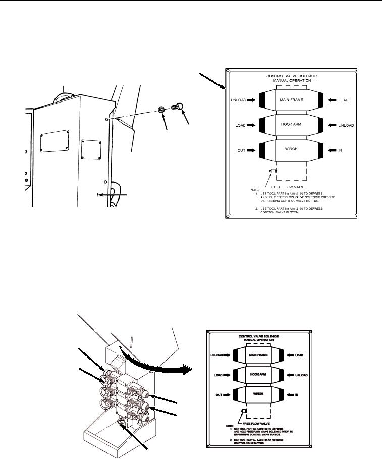
PERFORM PROCEDURE - Continued
15.
On disabled vehicle, remove four screws (Figure 8, Item 19), lockwashers (Figure 8, Item 20), and review data
plate (Figure 8, Item 18) inside of LHS control box cover (Figure 8, Item 17).
18
19
20
17
Figure 8.
Open M1977 A2 Cover.
NOTE
Button may be stiff and hard to push in.
16.
Press and hold free flow valve override button (Figure 9, Item 21). Simultaneously press one or more of the
following buttons to return LHS to the stowed position: hook arm LOAD (Figure 9, Item 22), hook arm UNLOAD
(Figure 9, Item 23), main frame LOAD (Figure 9, Item 24), main frame UNLOAD (Figure 9, Item 25).
25
22
24
23
21
Figure 9. Return LHS to Stowed Position.
03/15/2011Rel(1.8)root(opunuwp)wpno(O01052)