
TM 5-3990-263-13&P
0032
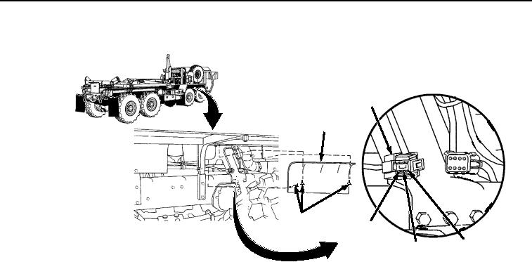
CORRECTIVE ACTION - Continued
P2
ACCESS
COVER
THUMB
POSITION
SCREWS
2
POSITION
POSITION
4
3
Figure 15. Connector P2.
7.
Place negative (-) probe of multimeter on position 35 of digital controller wiring harness connector
J4 (Figure 14).
8.
Place positive (+) probe of multimeter on position 3 of digital controller wiring harness connector
P2 (Figure 15). Check multimeter for continuity.
9.
Place negative (-) probe of multimeter on position 33 of digital controller wiring harness connector
J4 (Figure 14).
10.
Place positive (+) probe of multimeter on position 4 of digital controller wiring harness connector
P2 (Figure 15). Check multimeter for continuity.
a.
If continuity is not present at one or all of the readings, repair or replace digital controller
wiring harness. Refer to TM 9-2320-435-10 or TM 9-2320-425-10.
b.
If continuity is present for all of the readings, proceed to next Malfunction.
MALFUNCTION
Wiring Between Connector J3 and WINCH OUT Solenoid is Faulty (Model B Only).
CORRECTIVE ACTION
NOTE
Digital controller and cab control box are not repairable, therefore, it is necessary
to test digital controller and cab interface wiring harnesses, switches, solenoids,
and other components to identify possible faults other than digital controller and
digital cab controller.
1.
Remove connector from WINCH OUT solenoid (Figure 16).
03/15/2011Rel(1.8)root(tswp)wpno(T03028)