
TM 5-3990-263-13&P
0032
CORRECTIVE ACTION - Continued
POSITION
WINCH OUT
35
SOLENOID
J3
CONNECTOR
POSITION 1
POSITION 2
POSITION
5
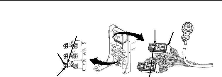
Figure 16. WINCH OUT Solenoid Connector and Connector J3.
CAUTION
Electrical power must be shut OFF from circuit before continuity can be checked.
Failure to comply with this caution may result in damage to test equipment or
electrical system.
NOTE
A reading of infinity indicates an open circuit.
2.
Set multimeter to ohms position.
3.
Place negative (-) probe of multimeter on position 5 of digital controller wiring harness connector
J3 (Figure 16).
4.
Place positive (+) probe of multimeter on position 1 of WINCH OUT solenoid connector
(Figure 16). Check multimeter for continuity.
5.
Place negative (-) probe of multimeter on position 35 of digital controller wiring harness connector
J3 (Figure 16).
6.
Place positive (+) probe of multimeter on position 2 of WINCH OUT solenoid connector
(Figure 16). Check multimeter for continuity.
a.
If continuity is not present at one or both readings, repair or replace digital controller wiring
harness. Refer to TM 9-2320-435-10 or TM 9-2320-425-10.
b.
If continuity is present for all of the readings, proceed to next Malfunction.
03/15/2011Rel(1.8)root(tswp)wpno(T03028)