
TM 5-3990-263-13&P
0038
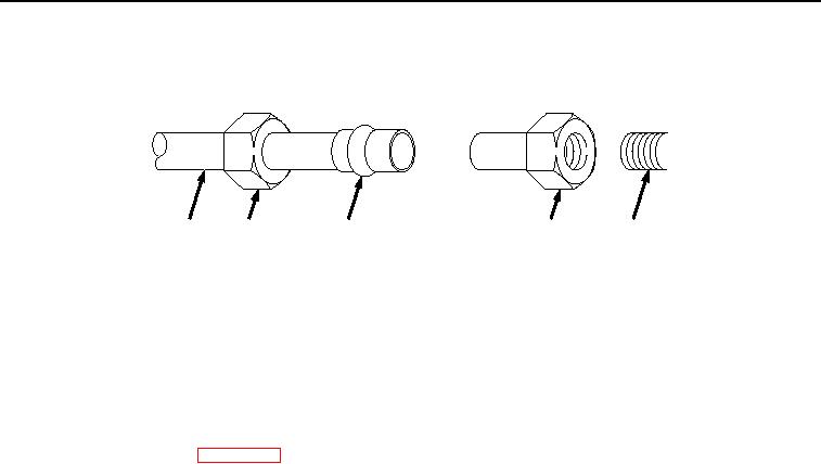
AIR TUBING - Continued
GENERAL AIR TUBING ASSEMBLY INSTRUCTIONS - Continued
1
2
3
2
4
Figure 1.
General Air Tubing Repair.
2.
Install tube nut (Figure 1, Item 2) and new flared tube sleeve (Figure 1, Item 3) on end of tube (Figure 1, Item
1), and install tube nut (Figure 1, Item 2) on fitting (Figure 1, Item 4). To finish installing flared tube sleeve
(Figure 1, Item 3), tighten tube nut (Figure 1, Item 2) by compressing flared tube sleeve (Figure 1, Item 3).
END OF TASK
FOLLOW-ON MAINTENANCE
1.
Load BAP on vehicle. (WP 0005)
2.
Check for air leaks.
END OF TASK
WELDING
GENERAL WELDING MAINTENANCE
Weldment Points
1.
Thoroughly inspect all weldments for cracks, chips, or other damage. BAP areas include the main frame
structure, winch frame structure, front pin lock assemblies, rear guides, center roller assembly, and catwalks.
2.
Not all weldments are specifically addressed below.
03/15/2011Rel(1.8)root(maintwp)wpno(M02176)