
TM 5-3990-263-13&P
0038
WELDING - Continued
Winch Frame Structure - Continued
6
8
6
6
7
1
5
2
2
4
4
3
3
3
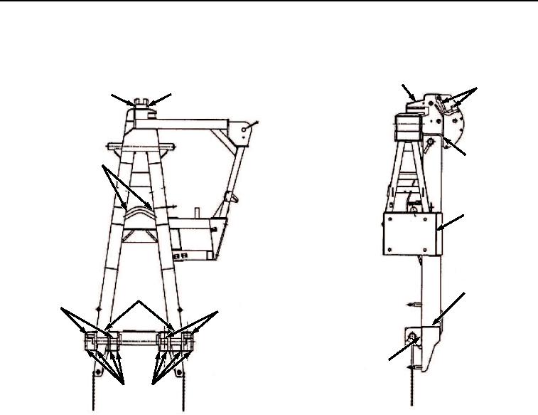
Figure 4. Winch Frame.
2.
Bottom Lock Beam to Side Tubes (Figure 4, Item 2). These welds join the bottom lock beam assembly to side
tubes. Sound welds in these joints are necessary to ensure safe handling of bridge bays and loaded BAP. A
crack should be repaired before it reaches 1.0 inch (25.4 mm) in length. The combined length of multiple cracks
at any joint should not exceed 2.0 inches (50.8 mm).
3.
Bottom Lock Support and Guide Plates to Beam (Figure 4, Item 3). These welds join the eight bottom lock
support and guide plates to the beam. Sound welds in these joints are necessary to ensure safe handling of
bridge bays and loaded BAP. A crack should be repaired before it reaches 1.0 inch (25.4 mm) in length. The
combined length of multiple cracks at any plate joint should not exceed 2.0 inches (50.8 mm).
4.
Bottom Locking Tabs to Pins (Figure 4, Item 4). These welds join locking tabs to bottom lockpins. Sound welds
are necessary to ensure safe handling of bridge bays and loaded BAP. A crack should be repaired before it
reaches 0.25 inch (6.4 mm) in length. The combined length of multiple cracks at any tab joint should not exceed
0.5 inch (12.7 mm).
5.
Winch Mounting Plate to Support Plate (Figure 4, Item 5). These welds join the winch mounting plate to support
plate coming from winch frame side tubes. Sound welds in these joints are necessary to ensure safe handling
of bridge bays. A crack should be repaired before it reaches 1.0 inch (25.4 mm) in length. The combined length
of multiple cracks in this joint should not exceed 2.0 inches (50.8 mm).
6.
Sheave Housing Side Plates to Cap Plate (Figure 4, Item 6). These welds join sheave housing side plates to
top cap plate. Sound welds in cap plate joints are necessary to ensure safe handling of bridge bays. A crack
03/15/2011Rel(1.8)root(maintwp)wpno(M02176)