
TM 5-3990-263-13&P
0041
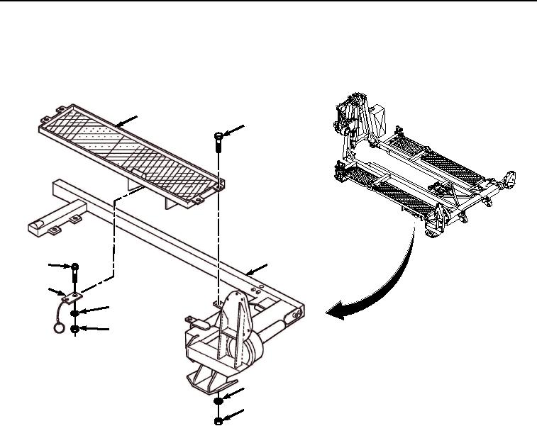
INSTALLATION - Continued
4.
Install four screws (Figure 6, Item 15), washers (Figure 6, Item 16), and locknuts (Figure 6, Item 17) on catwalk
(Figure 6, Item 1) and tube support (Figure 6, Item 6).
1
15
6
11
12
13
14
16
17
Figure 6. Catwalk Installation.
5.
Install screw (Figure 6, Item 11), retaining clip (Figure 6, Item 12), lockwasher (Figure 6, Item 13), and nut
(Figure 6, Item 14) on rear road-side section of catwalk (Figure 6, Item 1).
03/15/2011Rel(1.8)root(maintwp)wpno(M04035)