
TM 5-3990-263-13&P
FIELD MAINTENANCE
PLUNGER REPLACEMENT
INITIAL SETUP:
References
Tools and Special Tools
Tool Kit, General Mechanics: Automotive
Parts Manual (WP 0073, Figure 1)
(WP 0078, Table 2, Item 2)
Equipment Condition
Materials/Parts
Load removed from the BAP. (WP 0008)
Spring Pin (WP 0082, Table 1, Item 26)
BAP unloaded from the CBT. (WP 0006)
REMOVAL
1.
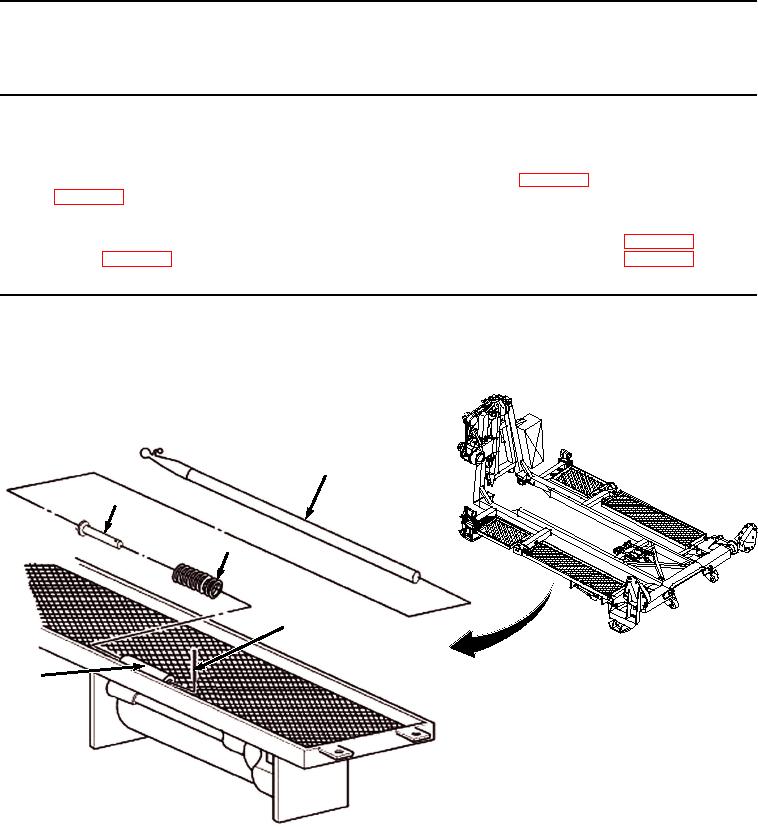
Remove boat hook (Figure 1, Item 1) from plunger housing (Figure 1, Item 2).
1
4
5
3
2
Figure 1. Plunger Removal.
2.
Remove spring pin (Figure 1, Item 3) from plunger (Figure 1, Item 4). Discard spring pin.
3.
Slide plunger (Figure 1, Item 4) out of plunger housing (Figure 1, Item 2).
4.
Remove compression spring (Figure 1, Item 5) from plunger (Figure 1, Item 4).
END OF TASK
03/15/2011Rel(1.8)root(maintwp)wpno(M04036)