
TM 5-3990-263-13&P
0065
INSTALLATION - Continued
22
41
38
40
40
39
29
47
45
46
42
30
37
28
36
35
27
26
32
29
33
34
31
44
43
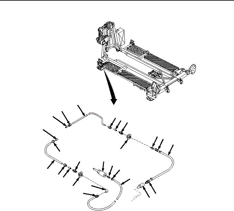
Figure 3.
Adapter and Clamps installation.
2.
Install fitting (Figure 3, Item 47) to coupling (Figure 3, Item 42).
3.
Install fitting connector (Figure 3, Item 45) on end of tubing (Figure 3, Item 46) to fitting (Figure 3, Item 47).
4.
Connect coupling half (Figure 3, Item 44) to coupling half (Figure 3, Item 43).
5.
Install fitting (Figure 3, Item 39) to coupling (Figure 3, Item 42).
6.
Install fitting connectors (Figure 3, Items 38 and 41) and ferrules (Figure 3, Item 40) on each end of tubing
(Figure 3, Item 22).
7.
Install fitting connector (Figure 3, Item 38) on end of tubing (Figure 3, Item 22) to fitting (Figure 3, Item 39).
8.
Install fitting (Figure 3, Item 36) to air cylinder (Figure 3, Item 37).
9.
Install air hose (Figure 3, Item 32) and clamp (Figure 3, Item 35) to fitting (Figure 3, Item 36) and tighten clamp
(Figure 3, Item 35).
10.
Install coupling (Figure 3, Item 34) to BAP frame.
03/15/2011Rel(1.8)root(maintwp)wpno(M04113)