
TM 5-3990-263-13&P
0065
INSTALLATION - Continued
9 5
7
24
23
3
2
1
4
16
15
21
14
6
8
11
9
13
10
12
22
25
24
17 18
19
20
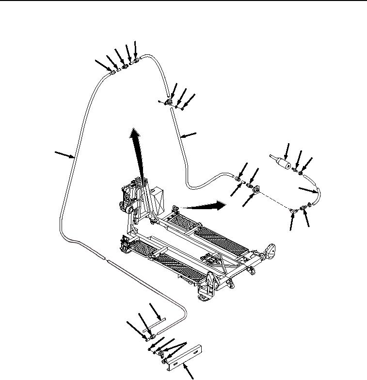
Figure 4. Coupling and Hose Installation.
16.
Install fitting connector (Figure 4, Item 23) on end of tubing (Figure 4, Item 21) to fitting (Figure 4, Item 7).
NOTE
Install loop clamps as noted prior to removal.
17.
Install bracket (Figure 4, Item 20) and four loop clamps (Figure 4, Item 19) on tubing (Figure 4, Item 21), tubing
(Figure 4, Item 22) and BAP frame with two nuts (Figure 4, Item 17) and lockwashers (Figure 4, Item 18).
18.
Install fitting (Figure 4, Item 15) to air cylinder (Figure 4, Item 16).
03/15/2011Rel(1.8)root(maintwp)wpno(M04113)