TM 5-3990-263-13&P
0012
OPERATION - Continued
30.
Release WINCH switch (Figure 11, Item 24) when cable hook holder (Figure 11, Item 31) is in saddle (Figure
11, Item 32).
NOTE
While continuing to move bridge bay forward, it may be necessary to adjust MAIN FRAME
switch to keep bridge bay properly positioned in BAP rear guides.
31.
Position remote MAIN FRAME switch (Figure 11, Item 23) to LOAD to bring bridge bay onto BAP rear rollers.
NOTE
If bridge bay fails to contact vehicle properly, partially unload bridge bay and repeat Step (31).
32.
Position HOOK ARM switch (Figure 11, Item 21) to UNLOAD as necessary to keep bridge bay positioned in
rear guide arms until cylinder (Figure 11, Item 22) is extended 6 in. (15 cm).
33.
Continue holding MAIN FRAME switch (Figure 11, Item 23) in LOAD position and release when main frame
is in stowed position.
34.
Set HIGH IDLE switch (Figure 11, Item 20) to OFF position.
35.
Position HOOK ARM switch (Figure 11, Item 21) to LOAD until LHS hook arm has been fully stowed.
36.
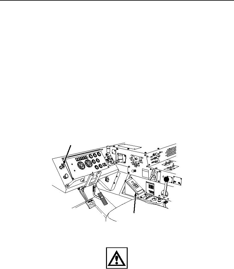
Push in PARKING BRAKE control (Figure 12, Item 25).
25
JACO
BS
ENGIN
E
BRAK
E
CAUT
ION
XHA
OE U
ILER Y
TRA PPILG
SU KN
AIR
PAR
FOR ND
NOT MIDLA
US
HTO
26
Figure 12. Brake and Transmission Controls.
WARNING
After water operations, vehicle brakes will be wet and will not stop as quickly as usual. Care
must be taken and extra distance allowed for slowing or stopping vehicle. Failure to comply
may result in serious injury or death to personnel and damage to equipment.
37.
Set transmission range selector (Figure 12, Item 26) to D (drive), and drive vehicle from the water.
38.
Pull out PARKING BRAKE control (Figure 12, Item 25).
03/15/2011Rel(1.8)root(opusualwp)wpno(O01061)

