
TM 5-3990-263-13&P
0012
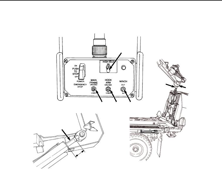
OPERATION - Continued
10.
Set HIGH IDLE switch (Figure 8, Item 20) to ON position.
20
31
32
23
21
24
22
s
he )
nc m
6i 5c
(1
Figure 8. Remote Control Unit Controls.
CAUTION
While moving LHS hook arm rearward, ensure BAP winch hydraulic hose lines are not
trapped or damaged. Failure to comply may result in damage to equipment.
11.
Position HOOK ARM switch (Figure 8, Item 21) to UNLOAD.
12.
Release HOOK ARM switch (Figure 8, Item 21) when cylinders (Figure 8, Item 22) are extended approximately
6 in. (15 cm).
13.
Position MAIN FRAME switch (Figure 8, Item 23) to UNLOAD and release when main frame is fully extended.
14.
Position HOOK ARM switch (Figure 8, Item 21) to UNLOAD and release when winch cable hook can be
reached from the ground.
03/15/2011Rel(1.8)root(opusualwp)wpno(O01061)