
TM 5-3990-263-13&P
0012
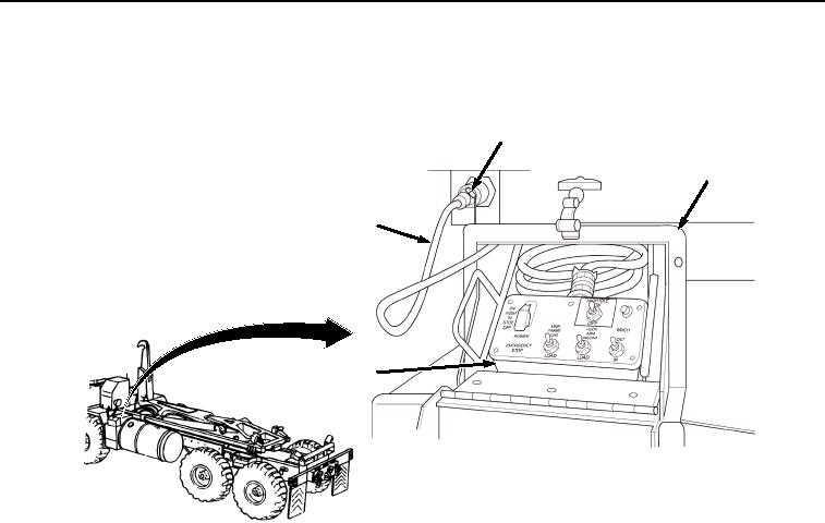
OPERATION - Continued
7.
Install remote control unit (Figure 6, Item 13):
16
15
14
13
SHOWN WITHOUT BAP INSTALLED
FOR CLARITY
Figure 6. Connect Remote Control Unit.
a.
Remove remote control unit (Figure 6, Item 13) and cable (Figure 6, Item 14) from stowage box (Figure
6, Item 15).
b.
Connect cable (Figure 6, Item 14) to curb-side or road-side LHS receptacle (Figure 6, Item 16).
8.
Turn LHS MODE SELECT switch (Figure 7, Item 17) to OFF.
03/15/2011Rel(1.8)root(opusualwp)wpno(O01061)