
TM 5-3990-263-13&P
0012
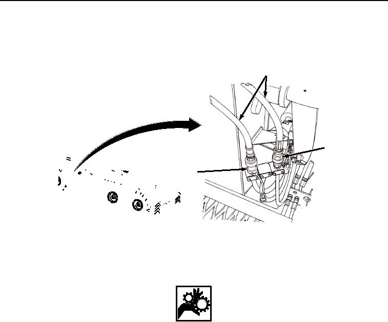
OPERATION - Continued
4.
Connect two winch hydraulic pressure hoses (Figure 3, Item 4) to male connector (Figure 3, Item 5) and female
connector (Figure 3, Item 6) located on bottom of hook arm assembly.
4
6
5
SHOWN WITHOUT BAP INSTALLED
FOR CLARITY
Figure 3. Connect Hydraulic Hoses.
WARNING
Keep hands and fingers clear of front pin lock assemblies when in the auto engaged and
disengaged position. Failure to comply may result in serious injury or death to personnel.
5.
Secure two front pin lock assemblies (Figure 4, Item 7) in the auto engage position. Pull back curb-side and
road-side pin lock assemblies (Figure 4, Item 7) until each latch lever pin (Figure 4, Item 8) rests in base of
vertical slot (Figure 4, Item 9).
03/15/2011Rel(1.8)root(opusualwp)wpno(O01061)