
TM 5-3990-263-13&P
0012
OPERATION - Continued
9
7
8
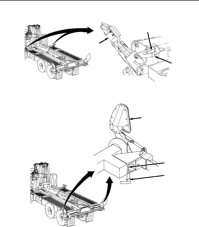
Figure 4.
Position Front Pin Locks.
6.
Secure curb-side and road-side rear guides (Figure 5, Item 10) in the engaged position.
10
12
11
Figure 5.
Position Rear Guides.
a.
Rotate latch pin (Figure 5, Item 11) and swing rear guide (Figure 5, Item 10) to the engaged (intermediate)
position.
b.
Ensure latch pin (Figure 5, Item 11) engages hole in rear bay guide (Figure 5, Item 12).
03/15/2011Rel(1.8)root(opusualwp)wpno(O01061)