
TM 5-3990-263-13&P
0012
OPERATION - Continued
39.
Set transmission range selector (Figure 12, Item 26) to N (neutral).
CAUTION
While maneuvering vehicle in the immediate vicinity of the loading or unloading site, LHS
MODE SELECT switch may be in any setting. However, LHS MODE SELECT switch must
be set to OFF/TRANSPORT prior to road travel. Failure to comply may result in damage to
equipment.
NOTE
Ensure both front pin lock assemblies are secured to bridge bay pins and both rear guides
are properly locked.
40.
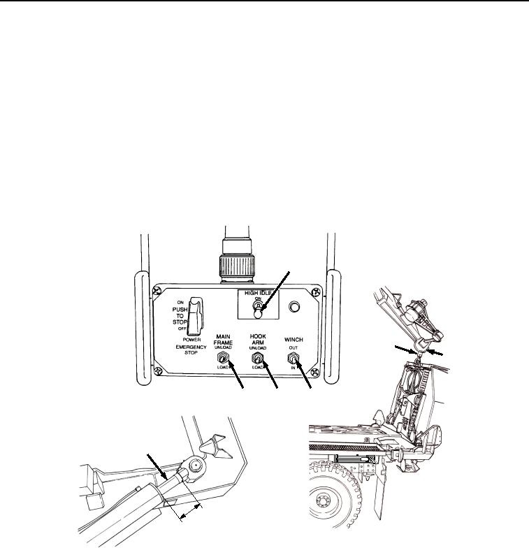
Position WINCH switch (Figure 13, Item 24) to OUT, and release when winch cable tension is released.
20
31
32
23
21
24
22
s
he )
c
in cm
6 5
(1
Figure 13. Remote Control Unit Controls.
41.
Set PTO ENGAGE switch (Figure 14, Item 18) to OFF position. Indicator light (Figure 14, Item 19) will go out.
03/15/2011Rel(1.8)root(opusualwp)wpno(O01061)