
TM 5-3990-263-13&P
0013
OPERATION - Continued
6.
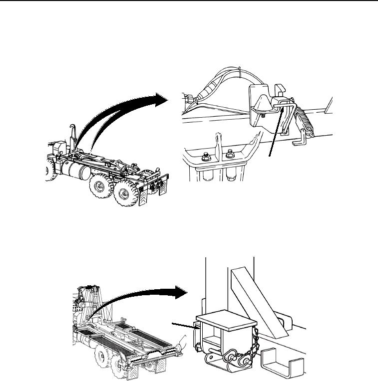
Ensure curb-side and road-side BAP hold-down lock handles (Figure 4, Item 8) are in the unlocked position
(handle pulled out).
8
SHOWN WITHOUT BAP INSTALLED
FOR CLARITY
Figure 4. Unlock BAP from CBT.
7.
Ensure both PLS feet (Figure 5, Item 9) are in the stowed position (up).
9
Figure 5. Position PLS Feet.
NOTE
Operation of each (road-side and curb-side) transload roller is the same.
8.
Deploy both BAP transload rollers (Figure 6, Item 10):
03/15/2011Rel(1.8)root(opusualwp)wpno(O01064)