
TM 5-3990-263-13&P
0030
CORRECTIVE ACTION - Continued
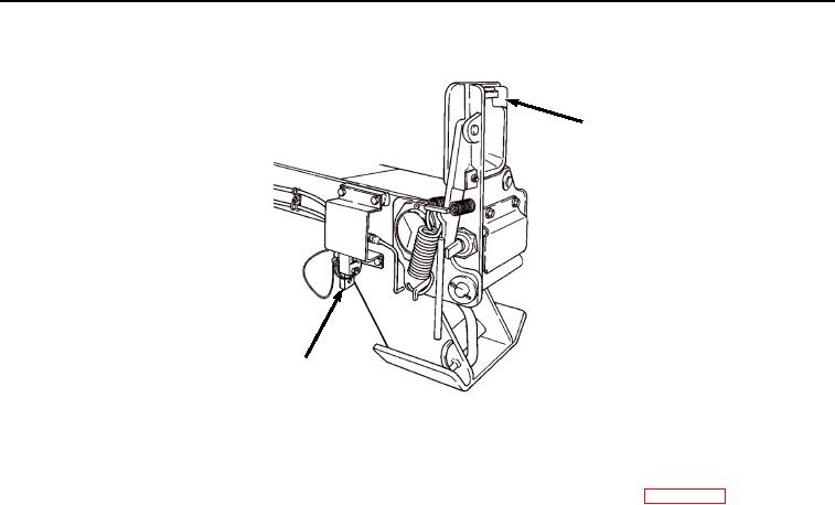
FRONT
PIN LOCK
LEVER
Figure 5.
Control Valve Lever.
a.
If very little or no air pressure is present, perform the following:
(1)
Replace hose(s) between control valve and air cylinder(s). (WP 0064)
(2)
Install air hose and adapter to road-side air cylinder and tighten hose clamp
(Figure 4).
(3)
Install air hose and adapter to curb-side air cylinder and tighten hose clamp
(Figure 4).
(4)
Install air cylinder guard to road-side front pin lock with two screws and lockwashers
(Figure 4).
(5)
Install air cylinder guard to curb-side front pin lock with two screws and lockwashers
(Figure 4).
(6)
Verify problem is corrected.
b.
If steady air pressure is present, perform the following:
(1)
Install air hose and adapter to road-side air cylinder and tighten hose clamp
(Figure 4).
(2)
Install air hose and adapter to curb-side air cylinder and tighten hose clamp
(Figure 4).
(3)
Proceed to next Malfunction.