
TM 5-3990-263-13&P
0030
MALFUNCTION
Control Valve is Faulty.
CORRECTIVE ACTION
NOTE
Air cylinders will not operate without sufficient air pressure output from control valve.
1.
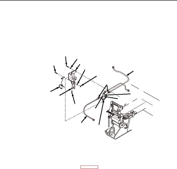
Remove air line fittings from right and left outlet ports of control valve (Figure 3).
SCREW (2 PLACES)
LOCKWASHER (2 PLACES)
SCREW
BRACKET
(2 PLACES)
LOCKWASHER
(2 PLACES)
AIR LINE
NUT (2 PLACES)
AIRLINE
FITTING
RIGHT
LANYARD
OUTLET
LOCKWASHER
PORT
CONTROL
(2 PLACES)
VALVE
SCREW
(2 PLACES)
LEFT
OUTLET
PORT
AIR LINE
PLUNGER
Figure 3. Control Valve Outlet Ports.
2.
Press plunger on bottom of control valve and check for air pressure at both outlet ports (Figure 3).
a.
If very little or no air pressure is present at one or both outlet ports, perform the following:
(1)
Replace control valve. (WP 0063)
(2)
Install fittings on left and right outlet ports of control valve (Figure 3).
(3)
Install bracket on control valve with two screws and lockwashers (Figure 3).
(4)
Install two screws and lockwashers on bracket and control valve (Figure 3).
(5)
Install lanyard, two screws, lockwashers, and nuts on bracket (Figure 3).
(6)
Verify problem is corrected.
b.
If steady air pressure is present from both outlet ports, perform the following:
(1)
Install fittings on left and right outlet ports of control valve (Figure 3).
(2)
Install bracket on control valve with two screws and lockwashers (Figure 3).
(3)
Install two screws and lockwashers on bracket and control valve (Figure 3).
(4)
Install lanyard, two screws, lockwashers, and nuts on bracket (Figure 3).