
TM 5-3990-263-13&P
0030
CORRECTIVE ACTION - Continued
(5)
Proceed to next Malfunction.
MALFUNCTION
Curb-side and/or Road-side Air Lines are Faulty.
CORRECTIVE ACTION
NOTE
Air cylinders will not operate without sufficient air pressure.
1.
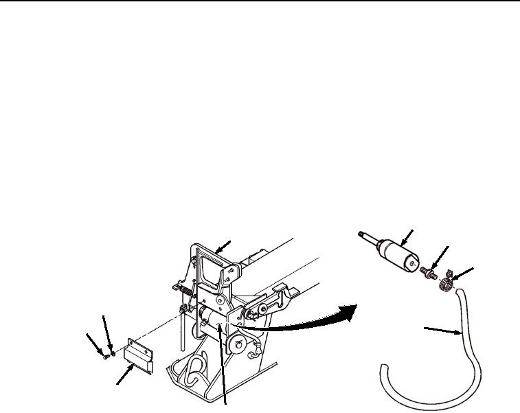
Remove two screws, lockwashers, and air cylinder guard from curb-side front pin lock (Figure 4).
Discard lockwashers.
FRONT
AIR CYLINDER
PIN LOCK
ADAPTER
HOSE
CLAMP
LOCKWASHER
AIR
SCREW
HOSE
AIR CYLINDER
GUARD
AIR CYLINDER
Figure 4. Air Cylinder.
2.
Remove two screws, lockwashers, and air cylinder guard from road-side front pin lock (Figure 4).
Discard lockwashers.
3.
Loosen hose clamp and remove air hose and adapter from curb-side air cylinder (Figure 4).
4.
Loosen hose clamp and remove air hose and adapter from road-side air cylinder (Figure 4).
5.
Pull lever (Figure 5) to activate control valve and check for air pressure at ends of hoses
(Figure 4).