
TM 5-3990-263-13&P
0032
CORRECTIVE ACTION - Continued
NOTE
A reading of infinity indicates an open circuit.
3.
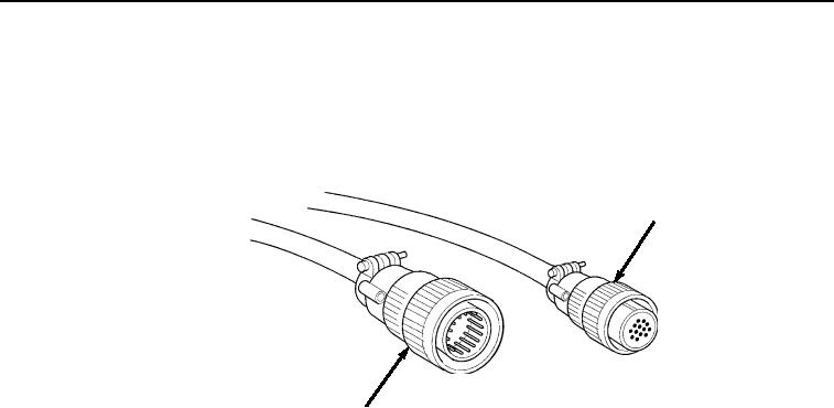
Place negative (-) probe of multimeter on position D of remote control cable connector P9
(Figure 5).
P9
P8
Figure 5. Remote Control Cable Connectors P8 And P9.
4.
Place positive (+) probe of multimeter on position C of remote control cable connector P8
(Figure 5). Check multimeter for continuity.
5.
Place negative (-) probe of multimeter on position E of remote control cable connector P9
(Figure 5).
6.
Place positive (+) probe of multimeter on position J of remote control cable connector P8
(Figure 5). Check multimeter for continuity.
a.
If continuity is not present at one or both readings, replace remote control cable.
Refer to TM 9-2320-435-10 or TM 9-2320-425-10.
b.
If continuity is present at both readings and vehicle is Model A, proceed to Malfunction
22 - 28 Volts Not Present At Position 33 On Main Frame Junction Box Terminal Strip
(Model A Only).
c.
If continuity is present at both readings and vehicle is Model B, proceed to Malfunction
Cab Interface Wiring Harness Is Faulty (Model B Only).
MALFUNCTION
Remote Linking Harness has Open Circuit on Side that does not Operate (Model A Only).
CORRECTIVE ACTION
1.
Open hydraulic cabinet cover. Refer to TM 9-2320-435-10 or TM 9-2320-425-10.
2.
Loosen four screws on main frame junction box cover and open cover. Refer to TM 9-2320-435-10
or TM 9-2320-425-10.
3.
If necessary, remove remote control cable from linking harness connector.