
TM 5-3990-263-13&P
0032
CORRECTIVE ACTION - Continued
CAUTION
Electrical power must be shut OFF from circuit before continuity can be checked.
Failure to comply with this caution may result in damage to test equipment or
electrical system.
4.
Set multimeter to ohms position.
NOTE
A reading of infinity indicates an open circuit.
Terminals to test are same on connector J8A (LH) and connector J8B (RH).
Test terminals of connector on side that does not operate.
5.
Place negative (-) probe of multimeter on terminal C of digital controller wiring harness connector
J8A (LH) or J8B (RH) (Figure 6).
LH LINKING
HARNESS
RH LINKING
CONNECTOR (J8A)
HARNESS
CONNECTOR (J8B)
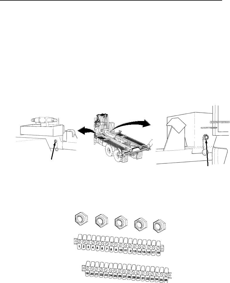
Figure 6.
Left (Connector J8A) and Right (Connector J8B) Remote Locations.
6.
Place positive (+) probe of multimeter on position 7 of main frame junction box (Figure 7). Check
multimeter for continuity.
Figure 7. Main Frame Junction Box (Wiring Removed For Clarity).