
TM 5-3990-263-13&P
0033
CORRECTIVE ACTION - Continued
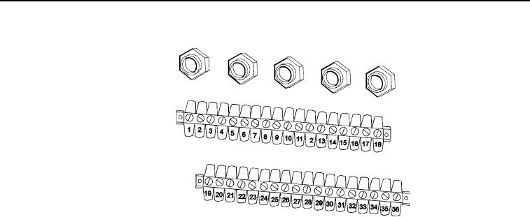
Figure 11. Main Frame Junction Box (Wiring Removed For Clarity).
4.
Place positive (+) probe of multimeter on position 1 of WINCH IN solenoid connector (Figure 10).
Check multimeter for continuity.
5.
Place negative (-) probe of multimeter on position 36 of main frame junction box terminal strip
(Figure 11).
6.
Place positive (+) probe of multimeter on position 2 of WINCH IN solenoid connector (Figure 10).
Check multimeter for continuity.
a.
If continuity is not present at one or both readings, replace WINCH IN solenoid wiring
harness. Refer to TM 9-2320-435-10 or TM 9-2320-425-10.
b.
If continuity is present for both readings, replace WINCH IN directional control valve.
Refer to TM 9-2320-435-10 or TM 9-2320-425-10.
MALFUNCTION
Cab Interface Wiring Harness is Faulty (Model B Only).
CORRECTIVE ACTION
1.
Remove three thumb screws and access cover on right side of vehicle under front fender to gain
access to cab interface wiring harness connector (Figure 12).
03/15/2011Rel(1.8)root(tswp)wpno(T03029)