
TM 5-3990-263-13&P
0033
CORRECTIVE ACTION - Continued
a.
If continuity is present for one or all readings, replace faulty remote linking wiring harness.
Refer to TM 9-2320-435-10 or TM 9-2320-425-10.
b.
If continuity is not present for all readings, fault not corrected. Notify supervisor.
MALFUNCTION
22 - 28 Volts not Present at Position 35 on Main Frame Junction Box Terminal Strip (Model A Only).
CORRECTIVE ACTION
1.
Open hydraulic cabinet cover. Refer to TM 9-2320-435-10 or TM 9-2320-425-10.
2.
Loosen four screws and remove cover from main frame junction box. Refer to TM 9-2320-435-10
or TM 9-2320-425-10.
3.
Turn engine start switch to ON position. Refer to TM 9-2320-435-10 or TM 9-2320-425-10.
4.
Turn light control switch to STOP LIGHT position. Refer to TM 9-2320-435-10 or TM
9-2320-425-10.
5.
Set multimeter to voltage position.
6.
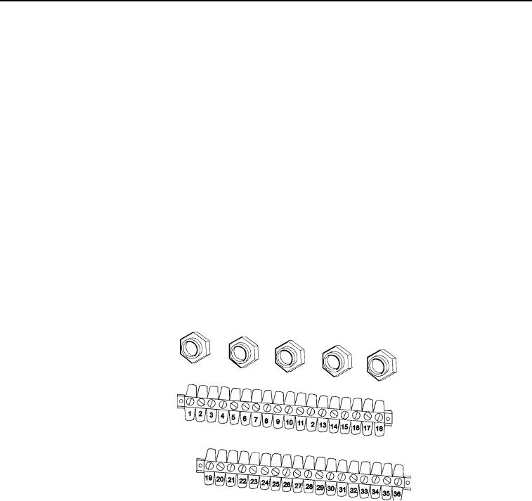
Place positive (+) probe of multimeter on position 35 of main frame junction box terminal strip
(Figure 9).
Figure 9. Main Frame Junction Box (Wiring Removed For Clarity).
7.
Place negative (-) probe of multimeter on known good ground. Check multimeter for voltage
reading while an assistant holds WINCH switch in IN position. Note reading.
8.
Instruct assistant to release WINCH switch.
9.
Turn engine start switch and light control switch to OFF position. Refer to TM 9-2320-435-10 or
TM 9-2320-425-10.
a.
If 22 - 28 volts is not present, remote control or remote control cable is faulty. Restart
procedure at Malfunction Winch Operates From One Side Of Vehicle But Not The Other.
b.
If 22 - 28 volts is present, proceed to next Malfunction.