
TM 5-3990-263-13&P
0033
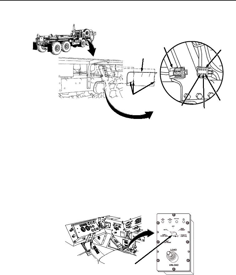
CORRECTIVE ACTION - Continued
P2
J2
ACCESS
COVER
THUMB
SCREWS
POSITION
POSITION
4
POSITION
2
3
Figure 12. Cab Interface Wiring Harness Access Cover.
2.
Cut and remove wire ties as necessary to loosen cab interface wiring harness.
3.
Disconnect cab interface wiring harness connector J2 from digital controller wiring harness
connector P2 (Figure 12).
4.
Turn engine start switch to ON position. Refer to TM 9-2320-435-10 or TM 9-2320-425-10.
5.
Set multimeter to voltage position.
6.
Place positive (+) probe of multimeter on position 2, circuit 1473, of cab control box connector J2
(Figure 12).
7.
Place negative (-) probe of multimeter on known good ground. Check multimeter for voltage
reading, note reading.
8.
Set LHS MODE SELECT switch to AUTO position (Figure 13).
JACO
BS
ENGIN
EBRA
KE
CAUT
ION
XHA
OE U
ILER Y
TRA PILG
RSUPND
N
ANIOTFORDPARK
ILA
M
US
HTO
CAB LHS MODE
SELECT SWITCH
Figure 13. Cab Digital Mode Select Switch.
9.
Place positive (+) probe of multimeter on position 3, circuit 1471, of cab control box connector J2
(Figure 12). Note reading.
03/15/2011Rel(1.8)root(tswp)wpno(T03029)