
TM 5-3990-263-13&P
0033
CORRECTIVE ACTION - Continued
MALFUNCTION
WINCH IN Solenoid Harness is Faulty (Model A Only).
CORRECTIVE ACTION
CAUTION
Electrical power must be shut OFF from circuit before continuity can be checked.
Failure to comply with this caution may result in damage to test equipment or
electrical system.
1.
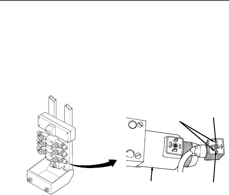
Remove connector from WINCH IN solenoid (Figure 10).
SOLENOID
CONNECTOR TEST
POSITION 2
POINTS
WINCH IN
POSITION 1
VALVE AND SOLENOID
Figure 10. WINCH IN Solenoid Connector.
2.
Set multimeter to ohms position.
NOTE
A reading of infinity indicates an open circuit.
Junction box terminal 35 is connected to one side of the solenoid and terminal
36 is connected to the other side of the solenoid.
3.
Place negative (-) probe of multimeter on position 35 of main frame junction box terminal strip
(Figure 11).