
TM 5-3990-263-13&P
0035
Table 1.
Operator Preventive Maintenance Checks and Services - Continued
ITEM TO BE
EQUIPMENT
ITEM
CHECKED OR
NOT READY/
NO.
INTERVAL
SERVICED
PROCEDURE
AVAILABLE IF:
4
3
2
1
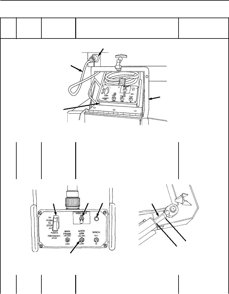
Figure 12.
Remote Control Unit.
Remove remote control cable (Figure 12, Item 3) and
connect it to left or right LHS receptacle (Figure 12, Item
4).
Ensure remote controls do not operate when remote
control EMERGENCY STOP switch (Figure 13, Item 5)
is in OFF position.
5
7
6
9
.
IN M)
6 C
5
(1
8
Figure 13.
Control Unit.
Turn remote control EMERGENCY STOP switch (Figure
13, Item 5) to ON position. Lamp (Figure 13, Item 6)
should light.
03/15/2011Rel(1.8)root(pmcswp)wpno(I04003)