
TM 5-3990-263-13&P
0035
Table 1.
Operator Preventive Maintenance Checks and Services - Continued
ITEM TO BE
EQUIPMENT
ITEM
CHECKED OR
NOT READY/
NO.
INTERVAL
SERVICED
PROCEDURE
AVAILABLE IF:
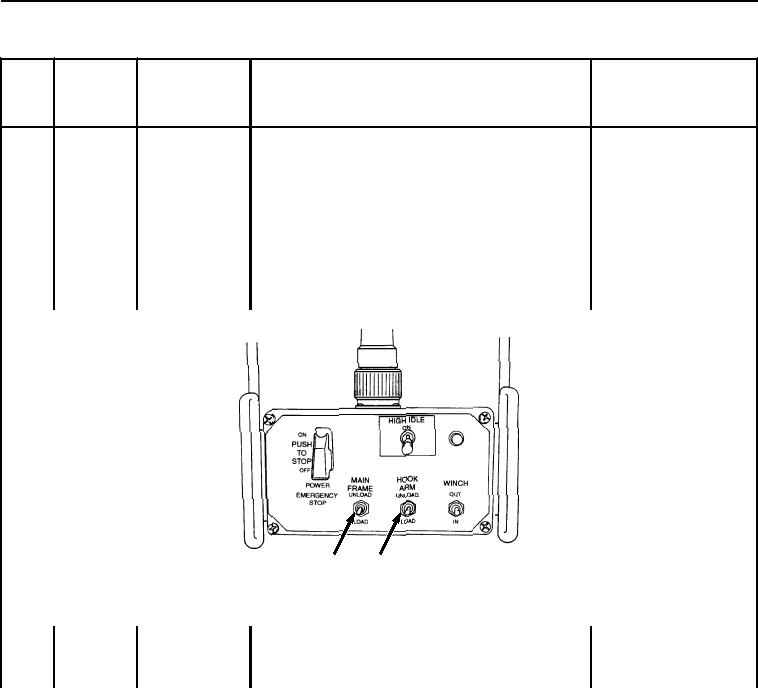
Position HIGH IDLE switch (Figure 13, Item 7) to ON.
Engine rpm should increase audibly. Turn HIGH IDLE
switch (Figure 13, Item 7) to OFF.
Position remote control HOOK ARM switch (Figure 13,
Item 8) to UNLOAD until hook arm cylinders (Figure 13,
Item 9) are extended approximately 6 inches (15 cm).
Position remote control MAIN FRAME switch (Figure 14,
Item 10) to UNLOAD and release when main frame is
extended fully. Ensure main frame extends fully.
10
8
Figure 14. Main Frame Switch.
Position HOOK ARM switch (Figure 15, Item 8) to
UNLOAD and release when winch cable hook (Figure
15, Item 11) can be reached from ground.
03/15/2011Rel(1.8)root(pmcswp)wpno(I04003)