
TM 5-3990-263-13&P
FIELD MAINTENANCE
CENTER ROLLER REPAIR
INITIAL SETUP:
References
Tools and Special Tools
Tool Kit, General Mechanics: Automotive
Parts Manual (WP 0073, Figure 4)
(WP 0078, Table 2, Item 2)
Equipment Condition
Center roller hydraulic cylinders and hoses
Materials/Parts
removed. (WP 0060)
Lockwasher (WP 0082, Table 1, Item 50) Qty: 1
Spring Pin (WP 0082, Table 1, Item 27) Qty: 4
REMOVAL
1.
Remove screw (Figure 1, Item 1), lockwasher (Figure 1, Item 2), straight-headed pin (Figure 1, Item 3), center
roller assembly (Figure 1, Item 4), and two thrust washers (Figure 1, Item 5) from center roller carriage (Figure
1, Item 6). Discard lockwasher.
11
10
12
9
7
8
6
9
10
7
2
5
1
13
4
3
5
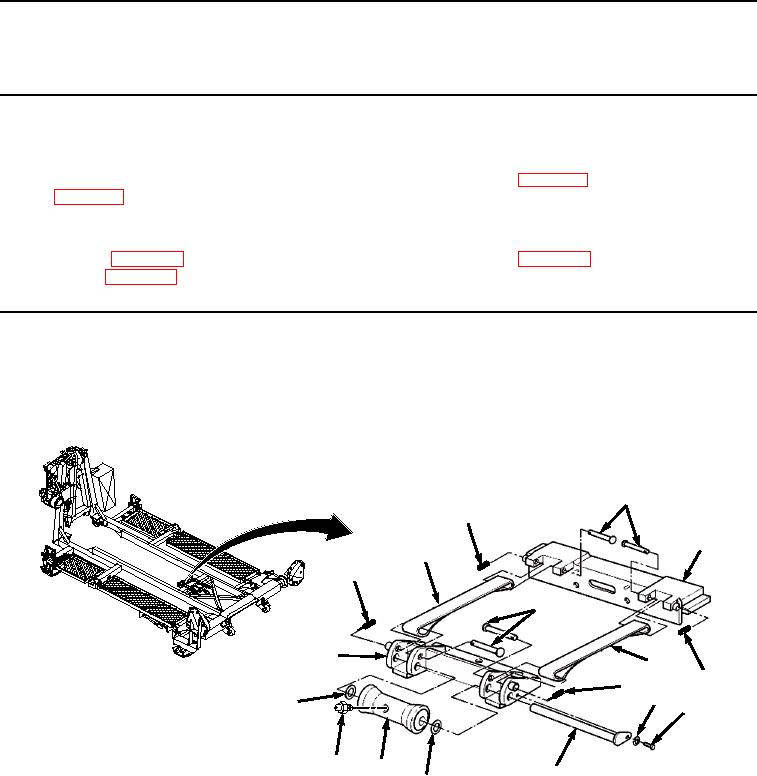
Figure 1.
Center Roller Removal.
2.
Remove two spring pins (Figure 1, Item 7) from two front strap pins (Figure 1, Item 8). Remove two strap pins
(Figure 1, Item 8) and pull straps (Figure 1, Item 9) from center roller carriage (Figure 1, Item 6). Remove center
roller carriage (Figure 1, Item 6) from the BAP. Discard spring pins.
3.
Remove two spring pins (Figure 1, Item 10) from two rear strap pins (Figure 1, Item 11). Remove two strap
pins (Figure 1, Item 11) and pull straps (Figure 1, Item 9) from rear cylinder carriage (Figure 1, Item 12). Remove
rear cylinder carriage (Figure 1, Item 12) from the BAP. Discard spring pins.
03/15/2011Rel(1.8)root(maintwp)wpno(M04039)