
TM 5-3990-263-13&P
0045
REMOVAL - Continued
13
26
8
19
18
21
12
14
20
17
16
17
11
15
24
25
22
23
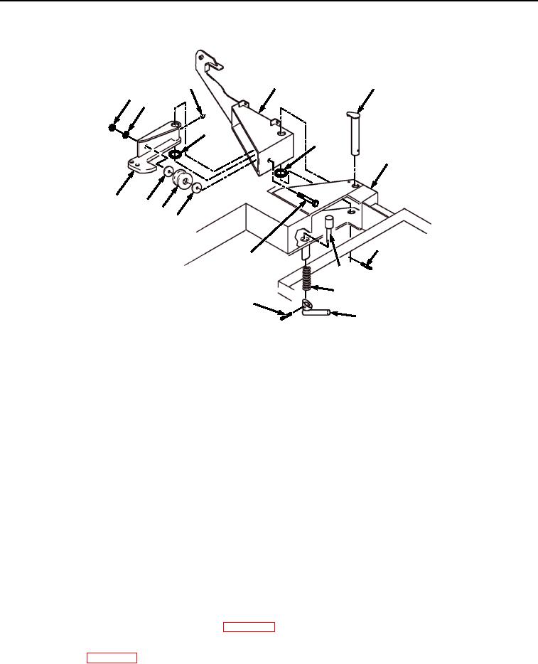
Figure 2.
Reaction Bracket Removal.
6.
Remove screw (Figure 2, Item 15), rubber bumper (Figure 2, Item 16), two spacers (Figure 2, Item 17), washer
(Figure 2, Item 18), and locknut (Figure 2, Item 19) from reaction bracket (Figure 2, Item 20) and lock bracket
(Figure 2, Item 8). Discard locknut.
7.
Remove reaction bracket (Figure 2, Item 20) and washer (Figure 2, Item 21) from lock bracket (Figure 2, Item
8).
8.
Remove spring pin (Figure 2, Item 22) from latch handle (Figure 2, Item 23). Remove latch handle (Figure 2,
Item 23) from latch pin (Figure 2, Item 24). Discard spring pin.
9.
Remove latch pin (Figure 2, Item 24) from frame (Figure 2, Item 14).
10.
Remove spring (Figure 2, Item 25) from latch pin (Figure 2, Item 24).
NOTE
Perform Step (11) if grease fitting is damaged.
11.
Remove grease fitting (Figure 2, Item 26) from reaction bracket (Figure 2, Item 20).
END OF TASK
CLEANING
1.
Refer to General Maintenance Instructions (WP 0038) for general cleaning instructions.
2.
Lubricate pivot pin (Figure 2, Item 13) and latch pin (Figure 2, Item 24) in accordance with Lubrication
Instructions (WP 0070).
END OF TASK
03/15/2011Rel(1.8)root(maintwp)wpno(M04040)