
TM 5-3990-263-13&P
0045
INSTALLATION - Continued
6.
Install screw (Figure 3, Item 15), rubber bumper (Figure 3, Item 16), two spacers (Figure 3, Item 17), washer
(Figure 3, Item 18), and locknut (Figure 3, Item 19) on reaction bracket (Figure 3, Item 20) and lock bracket
(Figure 3, Item 8).
7.
Install lock bracket (Figure 3, Item 8), washer (Figure 3, Item 12), screw (Figure 3, Item 9), and lockwasher
(Figure 3, Item 10) in rear guide (Figure 3, Item 4).
8.
Tap pivot pin (Figure 3, Item 13) into frame (Figure 3, Item 14).
9.
Install cotter pin (Figure 3, Item 11) on pivot pin (Figure 3, Item 13).
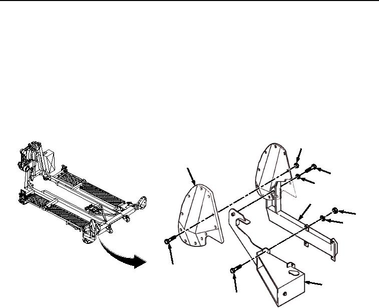
10.
Install lock bracket (Figure 4, Item 8) on rear guide (Figure 4, Item 4) with four screws (Figure 4, Item 5),
lockwashers (Figure 4, Item 6), and nuts (Figure 4, Item 7).
2
3
9
10
4
7
6
1
8
5
Figure 4.
Rear Guide Installation.
11.
Install rear guide pad (Figure 4, Item 3) on rear guide (Figure 4, Item 4) with 11 screws (Figure 4, Item 1) and
locknuts (Figure 4, Item 2).
END OF TASK
03/15/2011Rel(1.8)root(maintwp)wpno(M04040)