
TM 5-3990-263-13&P
FIELD MAINTENANCE
FRONT ROLLER ASSEMBLY REPLACEMENT
INITIAL SETUP:
Tools and Special Tools
References (cont.)
Tool Kit, General Mechanics: Automotive
(WP 0078, Table 2, Item 2)
Materials/Parts
Equipment Condition
Lockwasher (WP 0082, Table 1, Item 42) Qty:
2
Load removed from the BAP. (WP 0008)
BAP unloaded from the CBT. (WP 0006)
References
Parts Manual (WP 0073, Figure 6)
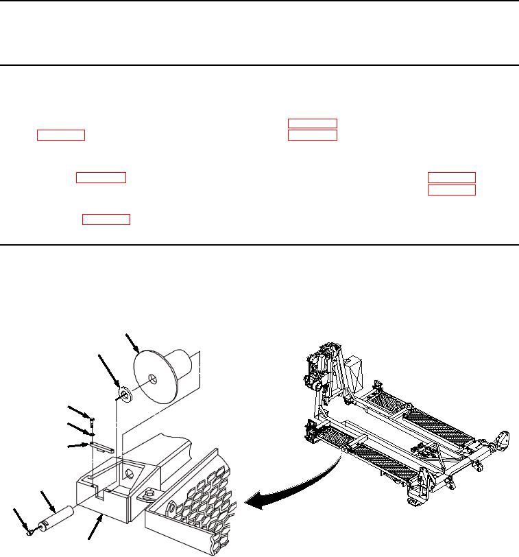
REMOVAL
1.
Remove two screws (Figure 1, Item 1) and lockwashers (Figure 1, Item 2) securing shaft cap (Figure 1, Item
3) to roller housing (Figure 1, Item 4). Discard lockwashers.
5
7
1
2
3
6
8
4
Figure 1.
Front Roller Assembly Removal.
2.
Using one hand to support front roller (Figure 1, Item 5), slide shaft (Figure 1, Item 6) out of roller housing
(Figure 1, Item 4), thrust washer (Figure 1, Item 7), and roller (Figure 1, Item 5).
3.
Remove front roller (Figure 1, Item 5) and thrust washer (Figure 1, Item 7) from roller housing (Figure 1, Item
4).
03/15/2011Rel(1.8)root(maintwp)wpno(M04041)