
TM 5-3990-263-13&P
0045
INSPECTION
1.
Refer to General Maintenance Instructions (WP 0038) for general inspection instructions.
NOTE
Rear guide pad prevents metal-to-metal contact between the BAP and bridge bay sections
during launch/recovery operations.
2.
Inspect rear guide pad (Figure 4, Item 3) for damage and/or wear. Replace rear guide pad (Figure 4, Item 3)
if worn within 1/16 inch (1.6 mm) from head of screws (Figure 4, Item 1) or exposes metal on rear guide (Figure
4, Item 4).
END OF TASK
INSTALLATION
NOTE
Perform Step (1) if grease fitting was removed.
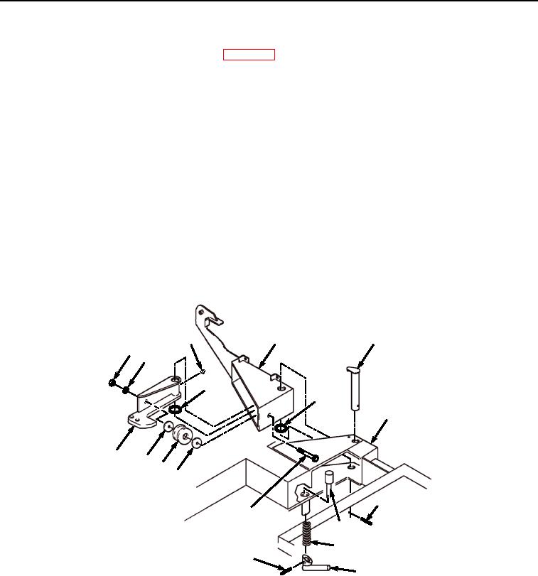
1.
Install grease fitting (Figure 3, Item 26) on reaction bracket (Figure 3, Item 20).
2.
Install spring (Figure 3, Item 25) on latch pin (Figure 3, Item 24).
13
26
8
19
18
21
12
14
20
17
16
17
11
15
24
25
22
23
Figure 3.
Reaction Bracket Installation.
3.
Install latch pin (Figure 3, Item 24) in frame (Figure 3, Item 14).
4.
Install latch handle (Figure 3, Item 23) on latch pin (Figure 3, Item 24), and install spring pin (Figure 3, Item
22) in latch handle (Figure 3, Item 23).
5.
Install reaction bracket (Figure 3, Item 20) and washer (Figure 3, Item 21) on lock bracket (Figure 3, Item 8).
03/15/2011Rel(1.8)root(maintwp)wpno(M04040)