
TM 5-3990-263-13&P
0050
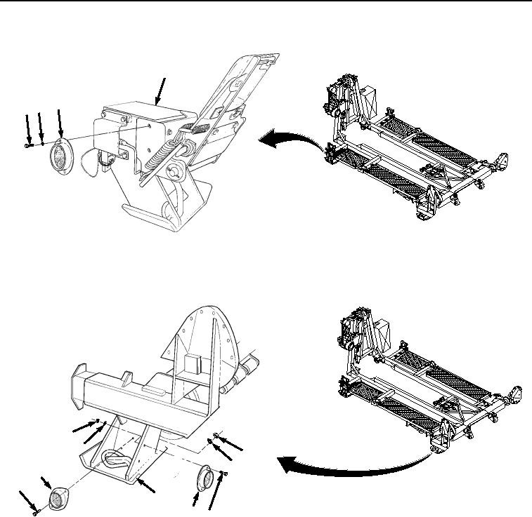
REMOVAL - Continued
9
8
67
Figure 2. Left Front Amber Reflector Removal.
3.
Remove two screws (Figure 3, Item 10), nuts (Figure 3, Item 11), lockwashers (Figure 3, Item 12), and red
reflector (Figure 3, Item 13) from BAP frame (Figure 3, Item 9). Discard lockwashers.
15
16
11
12
13
10
9
17 14
Figure 3.
Red Reflector Removal.
4.
Remove two screws (Figure 3, Item 14), nuts (Figure 3, Item 15), lockwashers (Figure 3, Item 16), and red
reflector (Figure 3, Item 17) from BAP frame (9). Discard lockwashers.
END OF TASK
INSTALLATION
NOTE
Steps (1) through (3) are the same for installation of road-side and curb-side reflectors.
03/15/2011Rel(1.8)root(maintwp)wpno(M04045)