
TM 5-3990-263-13&P
0049
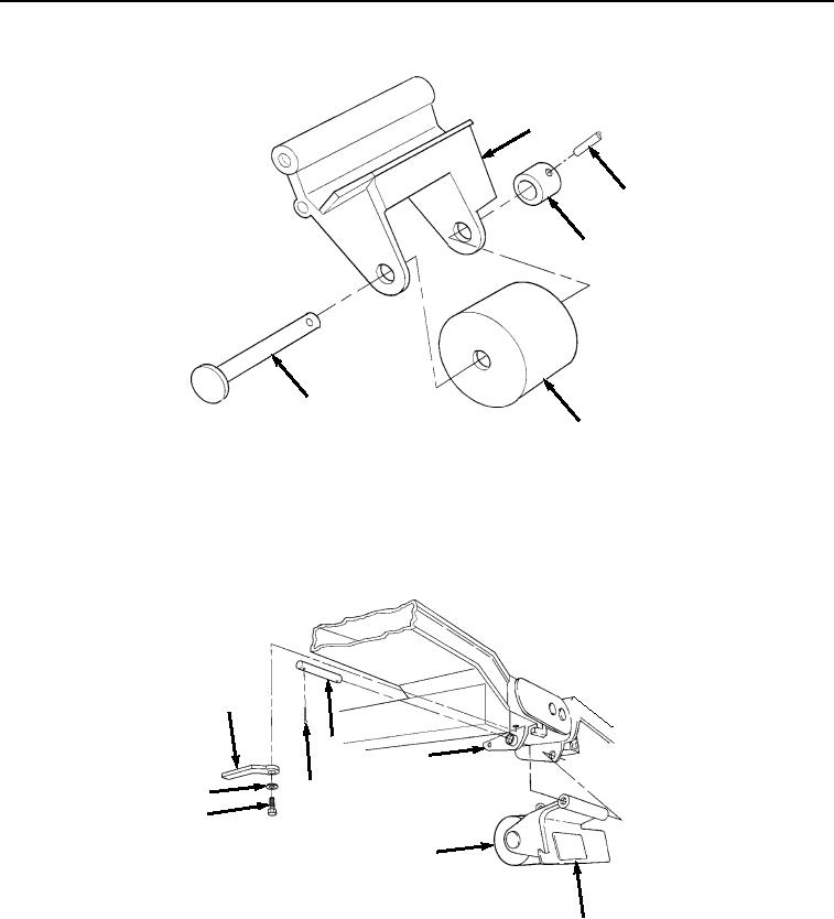
INSTALLATION - Continued
2
12
13
14
8
Figure 4. Transload Roller Pin Installation.
2.
Install spring pin (Figure 4, Item 12) in holes in transloader collar (Figure 4, Item 13) and headed pin (Figure
4, Item 14).
3.
Install retaining bar (Figure 5, Item 11), screw (Figure 5, Item 9), and lockwasher (Figure 5, Item 10) on welded
bracket on frame (Figure 5, Item 5).
11
7
5
6
10
9
8
2
Figure 5.
Transload Roller Installation.
4.
Install straight pin (Figure 5, Item 7) through transloader bracket (Figure 5, Item 2) and welded bracket on
frame (Figure 5, Item 5).
5.
Install cotter pin (Figure 5, Item 6) on straight pin (Figure 5, Item 7).
6.
Install lanyard (Figure 6, Item 4) on frame (Figure 6, Item 5) with screw (Figure 6, Item 3).
03/15/2011Rel(1.8)root(maintwp)wpno(M04044)