
TM 5-3990-263-13&P
0049
REMOVAL - Continued
11
7
5
6
10
9
8
2
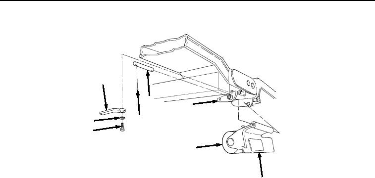
Figure 2. Transload Roller Removal.
NOTE
The straight pin is removed by pulling it toward the outside of the BAP.
3.
While an assistant supports transload roller (Figure 2, Item 8) and transloader bracket (Figure 2, Item 2),
remove straight pin (Figure 2, Item 7) from welded bracket on frame (Figure 2, Item 5) by pulling it toward the
outside of the BAP.
4.
Remove screw (Figure 2, Item 9), lockwasher (Figure 2, Item 10), and retaining bar (Figure 2, Item 11) from
welded bracket on frame (Figure 2, Item 5). Discard lockwasher.
5.
Remove spring pin (Figure 3, Item 12) and transloader collar (Figure 3, Item 13) from headed pin (Figure 3,
Item 14). Discard spring pin.
03/15/2011Rel(1.8)root(maintwp)wpno(M04044)